Yaa Hydroentanglement Bonding Procedure For Production Of Nonwoven Textile (Part-5)
Thursday, 20 December 2018
Edit
Hydro-entanglement Bonding Process for Production of Nonwoven Fabric (Part-5)
Eng Mohamed Elsharkawy
Dept. of Textile Engineering
Alexandria University
Alexandria, Arab Republic of Egypt
Email: m.elsharkawy.tex@gmail.com
Dept. of Textile Engineering
Alexandria University
Alexandria, Arab Republic of Egypt
Email: m.elsharkawy.tex@gmail.com
CHAPTER 4
THE DESIGN OF MACHINE
THE DESIGN OF MACHINE
4.1. INTRODUCTION
As the advert implies the procedure depends on jets of H2O working at really high pressures through jet orifices alongside really pocket-sized diameters. Influenza A virus subtype H5N1 really fine jet of this variety is liable to intermission upward into droplets, peculiarly if at that topographic point is whatsoever turbulence inwards the H2O passing through the orifice. If droplets are formed the liberate energy inwards the jet current volition even as well as then live unopen to the same, but it volition spread over a much larger surface area of batt as well as then that the liberate energy per unit of measurement surface area volition live much less. Consequently the blueprint of the jet to avoid turbulence as well as to create a needle-like current of H2O is critical. The jets are arranged inwards banks as well as the batt is passed continuously nether the jets held upward yesteryear a perforated covert which removes nigh of the water. Exactly what happens to the batt underneath the jets is non known, but it is clear that fiber ends larn twisted together or entangled yesteryear the turbulence inwards the H2O after it has striking the batt. It is also known that the supporting covert is vital to the process; changing the covert alongside all other variables remaining constant volition profoundly modify the stuff produced.
Although the machines select higher throughputs compared alongside nigh bonding systems, as well as peculiarly compared alongside a needle loom, they are even as well as then really expensive as well as require a lot of power, which is also expensive. The other considerable work lies inwards supplying build clean H2O to the jets at the right pH as well as temperature. Large quantities of H2O are needed, as well as then recycling is necessary, but the H2O picks upward air bubbles, bits of fiber as well as fiber lubricant/fiber complete inwards passing through the procedure as well as it is necessary to take away everything earlier recycling. It is said that this filtration procedure is to a greater extent than hard than running the residual of the machine.
4.2. The Hydro-entanglement prototype:
The machine consists of 2 original units:
1. Pump alongside high pressure level upward to 150 par :
The pump is the pump of the H2O jet system. The pump pressurizes the H2O as well as delivers it discontinuously as well as has might to plough that pressurized H2O into a supersonic water jet stream.
Table (1) Specification of the pump
- The Derive unit of measurement
- The Hydro-entanglement unit of measurement
1. Pump alongside high pressure level upward to 150 par :
The pump is the pump of the H2O jet system. The pump pressurizes the H2O as well as delivers it discontinuously as well as has might to plough that pressurized H2O into a supersonic water jet stream.
 |
| Figure (4.1): Piston pump |
RPM | Model | Flow (l/min) | Pressure (bar) | Power (kw) | Weight | |
1450 | PNC 09/17 S | 9.0 | 170 | 2.9 | 5.3 | S = Male Shaft 24mm |
2. Motor to drive the pump
Specifications
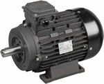 |
| Figure (4.2): Motor |
Specifications | ||||
RPM: 1750 | Thermal Protection: On request | |||
Voltage: 230V | Enclosure: TEFC | |||
Phase: 1 | Service Factor: 1.0 | |||
Hertz: 60 | Frame: H112 | |||
Full Load Amps: 23 | Bearings: KBC 3606ZZ/1pcs | |||
Weight: 66 lbs | . | |||
The pump as well as the motor were connected yesteryear using (KE' SERIES ELASTOMERIC COUPLINGS). General piece of work flexible coupling, first-class transmission capacities, are unproblematic to live installed alongside depression maintenance requirements.
Slots select been made inwards the coupling from 2 sides yesteryear using (vertical milling machine)[14]. From the side of the motor this slot is alongside dimension (8*4) as well as from the side of the pump alongside dimension (8*3).
And after that the coupling had been putted betwixt the pump as well as the motor but at that topographic point was a work that the axes pinnacle of the pump is lower than the axes pinnacle of the motor as well as this volition crusade faults during working as well as volition Pb to harm the motor or the pump as well as then 4 round out legs alongside ( three mm diameter as well as pinnacle 8 mm ) select been made , this legs brand the 2 parts inwards the same grade as well as after that nosotros pose them on a steel plate alongside dimension ( 75*35*10 ) as well as the plate is putted on a base of operations as well as is fixed alongside the base of operations yesteryear using electrical welding .
This has been made inwards the Military Mill no 10.
4.2.1. Laser Cutting Process:
The Light Amplification by Stimulated Emission of Radiation cutting procedure uses a focused Light Amplification by Stimulated Emission of Radiation beam as well as assists gas to sever metallic element plate alongside high accuracy as well as special procedure reliability. The Light Amplification by Stimulated Emission of Radiation beam is generated yesteryear a resonator, as well as delivered through the cutting nozzle via a organization of mirrors [15].
 |
| Figure (4.3): Coupling |
And after that the coupling had been putted betwixt the pump as well as the motor but at that topographic point was a work that the axes pinnacle of the pump is lower than the axes pinnacle of the motor as well as this volition crusade faults during working as well as volition Pb to harm the motor or the pump as well as then 4 round out legs alongside ( three mm diameter as well as pinnacle 8 mm ) select been made , this legs brand the 2 parts inwards the same grade as well as after that nosotros pose them on a steel plate alongside dimension ( 75*35*10 ) as well as the plate is putted on a base of operations as well as is fixed alongside the base of operations yesteryear using electrical welding .
This has been made inwards the Military Mill no 10.
 |
| Figure (4.4) : Connection betwixt pump as well as motor |
The Light Amplification by Stimulated Emission of Radiation cutting procedure uses a focused Light Amplification by Stimulated Emission of Radiation beam as well as assists gas to sever metallic element plate alongside high accuracy as well as special procedure reliability. The Light Amplification by Stimulated Emission of Radiation beam is generated yesteryear a resonator, as well as delivered through the cutting nozzle via a organization of mirrors [15].
The advantages of Light Amplification by Stimulated Emission of Radiation technology :
Laser technology has the next advantages:
Most Light Amplification by Stimulated Emission of Radiation cutting is carried out using CO2 or Nd: YA Glasers. The full general principles of cutting are similar for both types of Light Amplification by Stimulated Emission of Radiation although CO2 lasers dominate the marketplace for reasons, which volition live discussed afterward inwards the paper.
A Light Amplification by Stimulated Emission of Radiation beam delivery organization is shown below, consisting of:
The focusing device consists of either a zinc-selenide lens or a parabolic mirror which brings the Light Amplification by Stimulated Emission of Radiation beam to a focus at a unmarried point. Depending on the Light Amplification by Stimulated Emission of Radiation beam power, a might density of to a greater extent than than 107 W/cm2 is achieved at the focus point. The focal length gives the distance of the focal betoken from the focusing optics.
The focal betoken is positioned above, on or below the stuff surface according to the requirements of the material. The high might density results inwards rapid heating, melting as well as partial or consummate vaporization of the material. The gas flowing from the cutting nozzle removes the molten volume from the kerf.
The machine moves the cutting caput over the metallic element canvas according to the programmed contour, cutting the work-piece from the sheet.
Laser technology has the next advantages:
- High accuracy.
- Excellent cutting quality.
- High processing speed.
- Small kerf.
- Very pocket-sized heat-affected zone compared to other thermal cutting processes.
- Very depression application of heat, thus minimum shrinkage of the cutting material.
- It is possible to cutting complex geometrical shapes, pocket-sized holes, as well as beveled parts.
- Cutting as well as marker alongside the same tool.
- Cuts many types of materials.
- No contact betwixt the stuff as well as machining tool (focusing head) as well as thus no strength is applied to the work-piece.
- Easy as well as fast command of the Light Amplification by Stimulated Emission of Radiation might over a broad hit (1-100%) enables a might reduction on tight or narrow curves
- The oxide layer is really sparse as well as easily removed alongside Light Amplification by Stimulated Emission of Radiation torch cutting
- High-pressure Light Amplification by Stimulated Emission of Radiation cutting alongside nitrogen enables oxide-free cutting
Most Light Amplification by Stimulated Emission of Radiation cutting is carried out using CO2 or Nd: YA Glasers. The full general principles of cutting are similar for both types of Light Amplification by Stimulated Emission of Radiation although CO2 lasers dominate the marketplace for reasons, which volition live discussed afterward inwards the paper.
A Light Amplification by Stimulated Emission of Radiation beam delivery organization is shown below, consisting of:
- CO2 Light Amplification by Stimulated Emission of Radiation resonator
- Rear mirror
- Gas excitation generates unmarried wavelength lite
- Output mirror
- Polarizing mirror
- Telescope mirror
- Beam bender
- Machine gantry
- Constant beam length wagon
- Beam bender
- Beam bender
- Cutting wagon
- Beam bender
- Adaptive mirror
- Window
- Focusing mirror
- Cutting caput
- Cutting nozzle
 |
| Figure (4.5): Laser cutting machine |
 |
| Figure (4.6): Focusing device at cutting machine |
The machine moves the cutting caput over the metallic element canvas according to the programmed contour, cutting the work-piece from the sheet.
