Yaa Essential Parts Which Are Used Inwards Weft Insertion Displace Of Loom
Thursday, 20 December 2018
Edit
Essential Parts which are Used inwards Weft Insertion Motion of Loom

Bhavdip Paldiya
Dept. of Textile Technology
Sarvajanik College of Engineering & Technology, Surat, Bharat
Cell: +91 9662020909
Email: bhavdipk9009@gmail.com
Weft Insertion Motion
The motion of the inserted yarn inwards weft passage is a complex motion. It is called weft insertion motion. It is non a positively controlled process.
Here We Explain the Some Following Parts which are used inwards Weft Insertion Motion:
- Plate throttle tenser
- LH sensor
- Pre-winder
- Electromagnetic pivot
- Balloon sensor
- Balloon breaker
- ABS/WBS
- Tandem nozzle
- Main nozzle
- Electrical cutter
- Sub-nozzle
- H1 feeler
- H2 feller
- Thread a weft through the tenser. (Be certain to thread a weft between the foliage springs of the tenser.)
 |
| Plate throttle tenser |
Here,
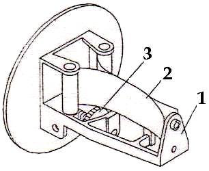
- Plate Spring Tenser
- Plate Spring
- Adjusting Nut
2. LH sensor:
3. Pre-winder:
4. Electromagnetic pin:
- This LH sensor detects the presence or absence of a weft yarn at the preset timing. If it detects a weft yarn, the machine continues running, if no weft yarn, the machines stop.
 |
| LH sensor |
- Adjust the drums superlative 1& ii at an equal distance from the horizontal centerline assumed betwixt tandem nozzles. Drums head 1& 2So that its centre job passes the centre of the inlet of tandem nozzle. Drums should live tilted downward fourteen score from a horizontal position.
- Right to left seat the electrical drum unit of measurement thus that the distance from balloon embrace to tandem nozzle comes to 50 mm. The distance from electromagnetic pivot to tandem nozzle should live approx 400-420 mm.
- Adjust drum caput 1& ii to the front end or bring upwards thus that its centre job passes the centre of tandem nozzle & chief nozzle. Adjust the height of chesses tensor in addition to eyelet front end to bring upwards positioning. By using force button, feed a weft yarn into the drum. Yarn feeding air is supplied from chief tank.
- Winding Sensor
- Electromagnetic Pin
- Measuring Band
- Measuring Bands
- Cover
- Motor
- Inlet Piece
- Winding Arm
- Push Button
- Adjust Bracket
 |
| Pre-winder |
- This pivot measures the length of a weft yarn for 1 pick. Make the clearance betwixt this pivot & measure band 0.5 to 0.8 mm.
 |
| Electromagnetic pin |
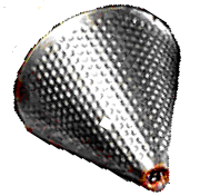
5. Balloon Sensor :
- This sensor observe the reveal of weft winding on measure bands in addition to is the get-go turn, 2nd (n-1)th turns in addition to nth turn. Adjust the clearance betwixt the sensor in addition to the measure band to 0.5 to 1.2 mm.
- Measuring length = Drawing inwards width + Waste selvedge inwards length.
- The balloon breaker makes the filling balloon little to cut down liberate tension in addition to filling insertion resistance. It is required to piece of work the loom stably amongst weak filling.
- It controls the balloon size in addition to pressure level of the main nozzle. It guides the weft thread,.
 |
| Balloon breaker |
- WBS Weft Brake System prevents broken picks in addition to slack picks.
- Braking forcefulness is applied to the filling simply earlier the insertion is completed. This reduces the velocity inwards club to greatly cut down peak tension. Decrease of broken picks improves character in addition to operation. Loom speed tin live increased.
 |
| Weft Break System |
- Broken Pick
- Slack Pick
- Intertwining
- Long & Short Pick
- High-Twisted And Elastic Yarn Returning
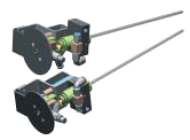
8. Tandem Nozzle:
- Set the crank angle at 90-degree . Set the dimension at 21 mm. Angle at most 10 score thus that tip in addition to of the accelerating metro of tandem nozzle comes to the centre job of chief nozzle. Up downward positioning at left accommodate tandem nozzle & thus that their centre lines passes the centre of drum caput 1&2 in addition to of thread guides respectively according to the next procedure.
- Adjust distance betwixt the top of tandem plate & the top of the tandem nozzle 1 bracket to 165mm & 2nd bracket to 60mm. Adjust the inclination of tandem nozzle & thus that the distance betwixt their tips becomes 48mm.
 |
| Tandem Nozzle |
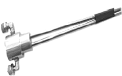
- The correct to left positioning of chief nozzle that accommodate slay thus that distance from its left halt to the left most dent of reed comes to 215 mm. Adjust chief nozzle so that distance from the tips of their acceleration tubes to the left most dent comes to approx xi mm.
- The criterion clearance betwixt thread lead & lock nut is approx 3.5 mm. build clean sides of thread lead & side of chief nozzle trunk amongst a build clean cloth or an air blower. Insert thread guide similar a shot into chief nozzle trunk until its locks teach engaged.
 |
| Main Nozzle |
10. Electrical Cutter:
The Electrical Cutter Solves The Difficulty Of Fine Adjustment.
The Electrical Cutter Solves The Difficulty Of Fine Adjustment.
- The cutter timing of the chief nozzle tin live onset the i-board. (Easy adjustment)
- The tension inwards filling cutting tin live adjusted according to the filling type fifty-fifty during operation.
- Because the cutter is inoperative during APR operation, it is unnecessary for the defective alternative to escape from the cutting area. (Easy adjustment for blowing-up, increment of success ratio of the APR)
- Sub nozzle is placed inwards front end of reed. Air is jetted inwards club to transfer the inserted weft through chief nozzle over the entire machine width. 4-sub valve is purpose inwards machine.
- Each sub valve has 4-sub nozzle bring together to it. Connect an air pipage to sub nozzles, thus tighten the nut fully past times hand. Rotate fixing nut by 360 score amongst a spanner. The superlative & angle of sub nozzle may live changed upon the texture type to live woven.
 |
| Sub nozzle |
***Arrangement of sub nozzle:
- Distance betwixt H1& H2 feller =125mm.
- Distance from the left most warp to the get-go sub nozzle =30mm.
- Distance betwixt sub nozzle inwards the key zone of textile =60mm.
- Distance from the correct most warp to the final sub nozzle = (30-60) mm.
- Distance betwixt final sub nozzle & H1 feeler = (25-30) mm.
 |
| Arrangement of sub nozzle |
12. H1 feeler.:
13. H2 feeler:
- H1 feeler detects the presence or absence of a weft yarn at the preset timing. If it detects a weft yarn,the machine continues running, if no weft yarn, the machines stop.
 |
| H1 feeler |
- H2 feeler detects the presence or absence of weft yarn at the preset timing. If it detects no weft yarn, the machine continues running, if it detects whatever weft yarn reaching the H2 due to a broken or blown-off weft problem the machine stop.
 |
| The Distance Between H1& H2 Feeler Is 125mm |