Now You Know Sliver Coiling Mechanism
Monday, 4 February 2019
Edit
Sliver Coiling Mechanism

Muhammad Ibrahim Khalilullah
Department of Textile Engineering
Daffodil International University
Facebook: https://www.facebook.com/ibrahim.khalil.002
Email: ibrahim23-3123@diu.edu.bd
Department of Textile Engineering
Daffodil International University
Facebook: https://www.facebook.com/ibrahim.khalil.002
Email: ibrahim23-3123@diu.edu.bd
Introduction:
The sliver must be coiled in cans for storage and transport. The storage is performed in a particular mechanism which is known as coiling mechanism.
Coiling
The process (Cyclonical deposition) by which the delivered sliver is uniformly deposited in a sliver can in an orderly manner is called coiling.
The slivers with out coil formation if drawn from the card sliver can to the draw frame then definitely the slivers will result in fuzz and apparently would have hampered the production . to reduce this problem coiling mechanism was introduced. It would have been very difficult if the slivers are deposited in the can straightly without coil formation.
Object of coiling mechanism
The figure shows the drive of coiler mechanism. The coiler get its drive from the bottom calendar roller shaft through a gear (H). This drives the vertical shaft through the bevel gear (G) and (F). At the top of vertical shaft there is another two bevel gear (I) and (1) through which coiler calendar roller gets the drive. The two coiler calendar rollers are being pressed together to form a nip below the coiler trumpet. The coiler calendar rollers are driven at surface speed slightly higher than that of the calendar rollers so that is a tension in the sliver. A tube wheel (7) driven by gear (D). On the vertical shaft has an inclined tube (6) with its upper end below the coiler calendar roller, so that it can collect the sliver from the nip of coiler calendar roller The lower end of the coiler tube is provided with an exit for the sliver at a point near its periphery, so that the sliver led is circular coil into the can. The can is positioned on a plate driven through reduction gearing from the bottom of the vertical shaft at a slow speed. The axis of the can is offset from that of the tube wheel.
Where,
Coiling
The process (Cyclonical deposition) by which the delivered sliver is uniformly deposited in a sliver can in an orderly manner is called coiling.
The slivers with out coil formation if drawn from the card sliver can to the draw frame then definitely the slivers will result in fuzz and apparently would have hampered the production . to reduce this problem coiling mechanism was introduced. It would have been very difficult if the slivers are deposited in the can straightly without coil formation.
Object of coiling mechanism
- The function of coiler mechanism is to lay the condensed sliver delivered by the calendar rollers in an orderly manner (Cycloidal deposition) in a cylindrical can.
- Sliver from the can may be pulled out at the next process without becoming entangled or stretched.
The figure shows the drive of coiler mechanism. The coiler get its drive from the bottom calendar roller shaft through a gear (H). This drives the vertical shaft through the bevel gear (G) and (F). At the top of vertical shaft there is another two bevel gear (I) and (1) through which coiler calendar roller gets the drive. The two coiler calendar rollers are being pressed together to form a nip below the coiler trumpet. The coiler calendar rollers are driven at surface speed slightly higher than that of the calendar rollers so that is a tension in the sliver. A tube wheel (7) driven by gear (D). On the vertical shaft has an inclined tube (6) with its upper end below the coiler calendar roller, so that it can collect the sliver from the nip of coiler calendar roller The lower end of the coiler tube is provided with an exit for the sliver at a point near its periphery, so that the sliver led is circular coil into the can. The can is positioned on a plate driven through reduction gearing from the bottom of the vertical shaft at a slow speed. The axis of the can is offset from that of the tube wheel.
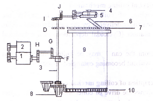 |
| Fig 01— Coiling Mechanism |
I- Bottom calendar roller, 2- Top calendar roller, 3 — vertical shaft, 4- Colier trumpet, 5-coiler calendar roller, 6- coiler tube , 7-Gear on coler tube, 8-Drive to the can plate, 9- can, l0- can plate gear
Laying down of silver
Cycloidal deposition of sliver has proved to be the most advantageous method of filling a can. In this process, two shifting movements of the deposition point are carried out simultaneously. As the coiler plate and the can, both are rotating, the delivered sliver continuously deposits in the can on a circle but the deposition point of the circle is constantly shifting. So a helical arrangement of the circles is produced within the can.
In some cases the cans are no longer rotated. The condition for this that both movements should be induced from the above. The can plate rotates at high speed in a second larger plate , which is also rotating but at a lower speed.Tbis also leads to shifting of the circles and hence to cycloidal deposition . In all situation , the sliver must be so deposited that a hollow space is created from top to bottom in the middle of the can. The space is required to ensure that the sliver layers do not overlap completely in the middle of the can. This avoids formation of a central pyramid-shaped column of material, leaving the side portions of the can half—empty. The diameter of the hollow space should be between about one-quarter and one-third of the diameter of the can.
Types of coiling
- Over centre coiling
- Under centre coiling
 |
| Fig01 - Over centre coiling |
The diameter relation should be =dc/db= 2.5 (apprx.)
2. Under centre coiling : Under centre coiling is the coiling a can where the dia of circle of the sliver is less than the radius of the can. Under centre coiling is used in larger diameter cans.
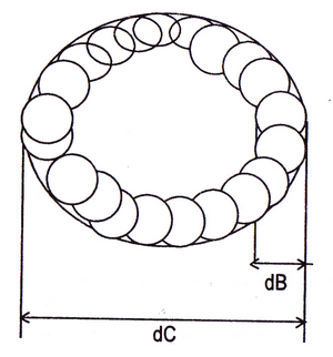 |
| Fig 02 - Under centre coiling |
The diameter relation should be =dc/db = 1.45 (apprx.)