Now You Know Rapid Prototyping and Free-form Deformation
Monday, 4 February 2019
Edit
Rapid Prototyping and Free-form Deformation

Bilal Rashid
Dept. of Garment Manufacturing
National Textile University, Faisalabad, Pakistan
Email: br.dmc.gcuf@gmail.com
RAPID PROTOTYPING:
DEFINITION:
Rapid prototyping is a group of techniques used to quickly fabricate a scale model of a physical part or assembly using three-dimensional computer aided design (CAD) data. Construction of the part or assembly is usually done using 3D printing or "additive layer manufacturing" technology.
Rapid prototyping is a group of techniques used to quickly fabricate a scale model of a physical part or assembly using three-dimensional computer aided design (CAD) data. Construction of the part or assembly is usually done using 3D printing or "additive layer manufacturing" technology.
COMPUTER AIDED DESIGN:
Computer-aided design (CAD) is the use of computer systems to assist in the creation, modification, analysis, or optimization of a design. CAD software is used to increase the productivity of the designer, improve the quality of design, improve communications through documentation, and to create a database for manufacturing. CAD output is often in the form of electronic files for print, machining, or other manufacturing operations. 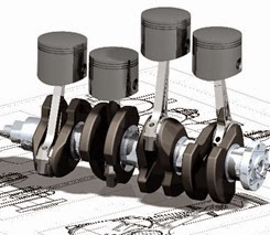 3D PRINTING:
Additive manufacturing or 3D printing is a process of making a three-dimensional solid object of virtually any shape from a digital model. 3D printing is achieved using an additive process, where successive layers of material are laid down in different shapes. 3D printing is also considered distinct from traditional machining techniques, which mostly rely on the removal of material by methods such as cutting or drilling (subtractive processes).
COMPREHENSIVE DETAILS:
Computer-aided design (CAD) is the use of computer systems to assist in the creation, modification, analysis, or optimization of a design. CAD software is used to increase the productivity of the designer, improve the quality of design, improve communications through documentation, and to create a database for manufacturing. CAD output is often in the form of electronic files for print, machining, or other manufacturing operations.

Additive manufacturing or 3D printing is a process of making a three-dimensional solid object of virtually any shape from a digital model. 3D printing is achieved using an additive process, where successive layers of material are laid down in different shapes. 3D printing is also considered distinct from traditional machining techniques, which mostly rely on the removal of material by methods such as cutting or drilling (subtractive processes).
 |
| Cutting |
- The first methods for rapid prototyping became available in the late 1980s and were used to produce models and prototype parts.
- Today, they are used for a wide range of applications and are used to manufacture production-quality parts in relatively small numbers if desired without the typical unfavorable short-run economics.
- This economy has encouraged online service bureaus.
- Historical surveys of RP technology start with discussions of simulacra production techniques used by 19th-century sculptors.
- Some modern sculptors use the progeny technology to produce exhibitions.
- The ability to reproduce designs from a dataset has given rise to issues of rights, as it is now possible to interpolate volumetric data from one dimensional image.
- For RP this data must represent a valid geometric model; namely, one whose boundary surfaces enclose a finite volume, contain no holes exposing the interior, and do not fold back on themselves.
- In other words, the object must have an “inside.” The model is valid if for each point in 3D space the computer can determine uniquely whether that point lies inside, on, or outside the boundary surface of the model.
- CAD post-processors will approximate the application vendors’ internal CAD geometric forms (e.g., B-splines) with a simplified mathematical form, which in turn is expressed in a specified data format which is a common feature in Additive Manufacturing: STL (stereolithography) a de facto standard for transferring solid geometric models to SFF machines.
- To obtain the necessary motion control trajectories to drive the actual SFF, Rapid Prototyping, 3D Printing or Additive Manufacturing mechanism, the prepared geometric model is typically sliced into layers, and the slices are scanned into lines [producing a "2D drawing" used to generate trajectory as in CNC`s toolpath], mimicking in reverse the layer-to-layer physical building process.
NOTE:
As with CNC subtractive methods, the computer-aided-design - computer-aided manufacturing CAD-CAM workflow in the traditional Rapid Prototyping process starts with the creation of geometric data, either as a 3D solid using a CAD workstation, or 2D slices using a scanning device.
As with CNC subtractive methods, the computer-aided-design - computer-aided manufacturing CAD-CAM workflow in the traditional Rapid Prototyping process starts with the creation of geometric data, either as a 3D solid using a CAD workstation, or 2D slices using a scanning device.
FREE-FORM DEFORMATION (FFD):
PREFACE:
The technique was first described by Thomas W. Sederberg and Scott R. Parry in 1986, and is based on an earlier technique by Alan Barr. It was extended by Coquillart to a technique described as extended free-form deformation, which refines the hull object by introducing additional geometry or by using different hull objects such as cylinders and prisms.
DEFINITION:
In computer graphics, free-form deformation (FFD) is a geometric technique used to model simple deformations of rigid objects. It is based on the idea of enclosing an object within a cube or another hull object, and transforming the object within the hull as the hull is deformed. Deformation of the hull is based on the concept of so-called hyper-patches, which are three-dimensional analogs of parametric curves such as Bézier curves, B-splines, or NURBs.
In computer graphics, free-form deformation (FFD) is a geometric technique used to model simple deformations of rigid objects. It is based on the idea of enclosing an object within a cube or another hull object, and transforming the object within the hull as the hull is deformed. Deformation of the hull is based on the concept of so-called hyper-patches, which are three-dimensional analogs of parametric curves such as Bézier curves, B-splines, or NURBs.
DEFORMATION (Engineering):
In materials science, deformation is a change in the shape or size of an object due to:
In materials science, deformation is a change in the shape or size of an object due to:
- An applied force (the deformation energy in this case is transferred through work) or
- A change in temperature (the deformation energy in this case is transferred through heat).
PARAMETRIC EQUATION:
In mathematics, a parametric equation of a curve is a representation of this curve through equations expressing the coordinates of the points of the curve as functions of a variable called a parameter. For example,  Is a parametric equation for the unit circle, where t is the parameter.
 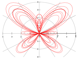 Non-uniform rational B-spline:
Non-uniform rational basis spline (NURBS) is a mathematical model commonly used in computer graphics for generating and representing curves and surfaces. It offers great flexibility and precision for handling both analytic (surfaces defined by common mathematical formulae) and modeled shapes.
In mathematics, a parametric equation of a curve is a representation of this curve through equations expressing the coordinates of the points of the curve as functions of a variable called a parameter. For example,


Non-uniform rational basis spline (NURBS) is a mathematical model commonly used in computer graphics for generating and representing curves and surfaces. It offers great flexibility and precision for handling both analytic (surfaces defined by common mathematical formulae) and modeled shapes.